|
|
High Laser-Induced-Damage Threshold Optics
2 e( W R7 U3 n: T3 W2 ?$ c' ~1 n8 ^8 o! z& s
What you need to know about laser damage before you buy laser optics – and what questions you need to ask your vendor.7 M# s- C/ R$ S q; F
$ U) W8 q! ?6 V) R6 K& I6 O
TREY TURNER, REO INC.
, C4 r, h8 T. D$ Z
4 K& H) p' ?# F E( g3 w+ }( GDespite nearly 50 years of study, laser damage continues to be a topic of some confusion for both optics manufacturers and consumers. Laser optics purchasers need to know the primary causes of damage and the steps that fabricators typically take to minimize them. They must engage in a meaningful dialogue with potential vendors to understand what questions to ask when qualifying a supplier.
6 ?) f% f7 p O
$ i9 C& ^$ [: H) KLaser damage regimes
9 h; K6 H/ T7 ~$ @/ G2 }; c S& E
9 K+ V% ^7 E7 I$ h+ _Damage is a problem in virtually every wavelength regime in which lasers operate. However, the damage mechanisms of lasers operating in the visible and near-visible spectra are distinct from those of lasers operating in the far-infrared and deep-ultraviolet. For brevity, this article will concentrate on lasers operating in the visible, near-ultraviolet and near-infrared. Within this range, it is useful to further categorize lasers according to their temporal characteristics: namely, ultrafast, nanosecond and continuous wave.
* Q( t8 m2 V7 F9 h, j4 m( ~- N
5 _. y) [) h% C6 W/ c8 l
An operator loads an optic into REO’s automated damage test system, which enables testing at 1064 nm with either 3- or 20-ns pulse durations at pulse energies of up to 50 J/cm2. Images courtesy of REO Inc.
6 W: q+ n8 h+ @# L" I# J6 a& p
For all these laser types, damage is usually defect-related; however, the way in which damage occurs depends upon the operating regime. Ultrafast (pico- and femtosecond) lasers typically produce high peak powers and low energy per pulse; furthermore, the time between pulses is long compared to the pulse duration itself. Consequently, the primary cause of damage in ultrafast optics is usually related to instantaneous field strength, rather than to total pulse energy. Specifically, the electric fields present in ultrafast pulses can be sufficiently high to cause dielectric breakdown of a defect or even the thin-film materials, resulting in arcing and damage. Generally, there isn’t adequate energy in an individual ultrafast laser pulse to heat a defect enough to cause purely thermal damage, and there usually is plenty of time between pulses for heat to be conducted out of the defect into surrounding material, so there is no heat buildup over time.
- t: I6 l$ Z2 r# O4 ]& }0 _* M9 j: u1 q& U2 i
Nanosecond-regime lasers typically operate by Q-switching and produce pulse durations in the 100-ps to 100-ns range, with repetition rates in the tens of hertz to hundreds of kilohertz. Under these circumstances, damage usually occurs by absorption, heating and, ultimately, vaporization of defects and the surrounding material. As a result of complex thermal and mechanical interactions between the defect materials and the coating materials, coating materials with the lowest absorption do not necessarily yield thin films with the highest damage threshold.5 Q( k+ K: N; z* |/ ?2 C- ^1 ?
0 A, D7 j" e0 m! z
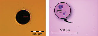
One additional complexity of specifying and producing high laser-induced-damage threshold optics is that defects that may induce laser damage can be very small. Depending upon its composition and absorption characteristics, a defect of only a few tens of nanometers – invisible to standard inspection equipment – can be problematic.
4 r( N/ J0 J" ~/ ~+ c" [
9 e( M+ m4 M, R- n) w7 u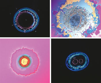
Lasers can cause a lot of damage to optical coatings, and buyers of optics would do well to understand laser-induced damage and how to avoid it. Images courtesy of Alex Martin, REO Inc.
9 m& r8 j7 Y+ c( t3 w+ \
Thus, for nanosecond-regime lasers, damage is dependent upon total laser pulse energy, material absorption and thermomechanical characteristics of both the coating materials and defects, and defect distribution. Repetition rate also becomes significant when it is shorter than the time necessary for heat to be conducted away from absorbing defects.
4 ]* e9 b M$ O7 p5 L+ a. Y. ]# K& m6 d
For lasers that are CW or quasi-CW, the absorption characteristics of defects and coating materials are the main determining factor in damage. Because there is no thermal recovery period, damage initiated at a small defect by a high CW fluence will often spread to include surrounding areas until the entire region within the high-fluence beam area has been damaged catastrophically.( r3 @: w& A1 K) [3 ?- ]
t0 e2 E& y, u$ l$ `: P" Y
(Left) CW laser damage caused by a 1-MW/cm2 beam at 1030 nm. The damage site propagates to cover the entire size of the beam. (Right) Numerous pulsed-laser damage sites, caused by a 27-J/cm2 pulse at 1064 nm. Damage does not propagate, and each site is relatively small.
" J7 N ^$ N6 R4 QFabrication issues$ F# a l# p/ j4 c: a
) b2 m/ g3 k+ l# a! K
A variety of defects that can cause laser damage are introduced at each stage of the manufacturing process. Thus, it is worthwhile to review in detail the sources of the defects, as well as the fabrication, cleaning and coating methods that eliminate them.0 p4 O2 ^8 j1 w: b( z9 q
4 i1 s$ N6 r$ h" {6 oOne problem that occurs during component fabrication is subsurface damage. This consists of fractures and scratches caused by the various grinding and polishing processes, which become partially or totally hidden during subsequent fabrication steps. It has been shown that a thin layer of the substrate material – the Beilby layer – can reflow while the piece is being polished, sealing these defects below the final surface. Subsurface damage can reduce the damage threshold by providing a place for light-absorbing contaminants to reside, by allowing atoms at or near the fractures to be more easily ionized, and by causing local intense modulations in the electromagnetic field.
9 b* j1 d# T" |1 \7 Q# q! h S! {
; R% U/ V/ W* u: w eThe fabricator can take a couple of approaches to minimize subsurface damage. First, grinding and polishing should occur in a series of small steps in which the size of the grit used is decreased gradually, rather than in large increments. Specifically, each polishing step should remove enough material to eliminate the fractures from the previous step without itself producing any that are larger than those from the previous. Superpolishing is also a useful technique for fabricating high-damage-threshold optics. The term “superpolishing” broadly refers to any method that yields very low surface roughness, <1 Å rms.. A- V/ k' r0 t- ?5 G
8 x- e5 E+ i- n# H$ j+ T$ o ~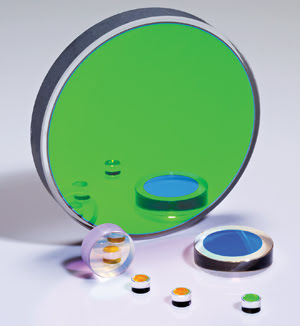
High laser-induced-damage threshold optics are produced over a wide range of sizes and spectral ranges.
0 o, t+ K4 r1 \! d7 r2 m( Y) VCleaning of optical surfaces, particularly just prior to coating, is a critical step. The goal is to remove contaminants from the optical surface before they are sealed in by the coating. The types of contaminants found in a typical fabrication environment can generally be classified as either particulates or organics., d0 R4 _. D/ ]
1 F7 Q2 T/ P m8 e- s {- l
Particulates are things like residue from the polishing process and dust; these are usually removed with detergent cleaning chemistries and ultrasonic techniques. Organics are often airborne contaminants or surface residuals from earlier cleaning and blocking processes. Typical examples are human sweat, finger oils, blocking wax, adhesives and organic cleaning solvents. These are usually removed with other organic solvents and detergents. The takeaway here is that a variety of cleaning techniques must be employed to thoroughly prepare a surface for coating.; k1 }& H V4 ~
( ^; j3 m$ {* C2 P
Control of the production environment to eliminate sources of contamination is also critical. The best practice is for the entire cleaning and coating process to occur in a cleanroom, rather than under a laminar flow hood. Furthermore, it is highly advantageous to work with a vendor that can fabricate and coat in a single facility, eliminating the potential contamination from packing, shipping and unpacking steps.& g a& Y1 b0 X6 k |& l
3 ^0 E& g1 n5 K8 g) y* z# _
Coating considerations
" ~; ^$ K% ^# g9 ?: s0 ?% G- J5 z
Currently, high-damage-threshold coatings are made using a variety of deposition processes, including various evaporative techniques and sputtering methods. Most coating manufacturers tend to employ a single method and therefore try to convince customers that their chosen approach is uniquely suited to delivering high-damage-threshold thin films. At REO, we have ion beam sputtering (IBS), ion-assisted deposition processes and traditional evaporative methods at our disposal, so we can afford to be unprejudiced in evaluating various coating techniques.
* R- B& w5 V: d: t3 u0 L
. }) x: ^7 m& j2 {# vMost of REO’s high-damage-threshold coatings are produced using IBS because it yields fully densified films that, after they are formed, are essentially impervious to the absorption of contaminants. Also, a properly managed IBS process creates films with relatively few internal defects. Thus, IBS films will generally not damage readily. However, because they do exhibit relatively high internal stress, once damage is initiated in a dense film, it is likely to be catastrophic.; N9 ]( [7 T* D0 Y( b2 M* o
# x5 w$ v3 z) I# S
In contrast, the coatings produced with evaporative techniques are relatively porous and contain low internal stress, which makes damage sites grow more slowly than in a denser film. But this porosity also allows higher levels of particulate contamination within the film, as well as entry of water or volatile organics. A porous film can absorb airborne molecular contaminants even during use. Furthermore, during the evaporative process itself, liquefied coating material can spatter onto the film, producing elements that aren’t stoichiometric and therefore are absorbers.
. n4 ]% c# A+ x- g
0 J1 u. h6 [3 j6 J0 C0 _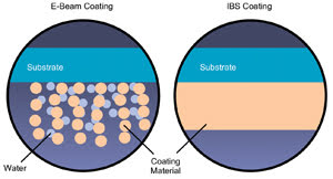
Electron beam deposition (left) produces porous, low-density columnar coatings subject to water absorption. Ion beam sputtering deposition (right) yields fully densified coatings with virtually no water absorption.
0 S) z, }! j/ d; K2 cDamage testing. z+ `/ z' F M9 \
2 G$ @* N2 @3 x- ^% Y
Unfortunately, despite the best efforts of optics manufacturers to control their fabrication, cleaning and coating operations so as to maximize damage resistance, there are still many contributing factors that occur intermittently and that aren’t well controlled or understood. This means that statistical quality control methods that rely on relatively small sample sizes can’t be effectively applied. Thus, extensive testing on virtually every coating run often must be performed to determine damage characteristics. However, laser damage testing is time-consuming and destructive, so there is a clear trade-off between establishing confidence and production cost.
0 R6 K) k5 O6 Z4 A1 w
/ w/ C/ s5 d3 G# o. [It is important to understand the exact protocols and methods that a vendor uses to damage test its optics. The number of parts tested, the number of individual sites tested per part, and the type of part (witness piece or actual production unit) should all be ascertained. The specifics of the test setup (laser type, wavelength, pulse energy), the controls used (pulse energy and beam profile measurements), and compliance with ISO testing standards should all be discussed. It can also be advantageous to work with a vendor who has in-house damage testing, because this generally avoids the detrimental effects introduced by product shipping and handling, and the environment at the test facility; it also enables more cost-effective testing of a larger number of parts.
4 M/ j3 Z, i* I9 O) d5 _" M7 i9 f6 J l) h
As long as manufacturers and users of lasers continue to strive for ever-higher powers and ever-smaller footprints, laser damage will be with us. However, working with suppliers to understand the specific steps they take to control and minimize the sources of damage will give buyers more realistic expectations and better outcomes.
T0 E! R# w) ]& Q4 Y7 j
9 e$ p2 s& W8 j# ]0 Q) `- t* _, r/ qMeet the author
0 h- z3 B, _+ g0 A9 o
* w6 R' R6 Y" L+ `3 P/ Q8 K8 }Trey Turner is vice president of technology at REO Inc. in Boulder, Colo.; e-mail: treyt@reoinc.com.
6 U' i* U N8 ^: I$ f |
|

 窥视卡
窥视卡 雷达卡
雷达卡 发表于 2020-5-2 02:33:01
 提升卡
提升卡 置顶卡
置顶卡 沉默卡
沉默卡 喧嚣卡
喧嚣卡 变色卡
变色卡 抢沙发
抢沙发 显身卡
显身卡