|
|
- J/ Z4 `1 \+ u* C: ^ q[size=+3]Triple Bandpass Filter for OIC Contest # D$ w6 R8 n% }$ |$ [7 d
% E" V Y3 d5 Z3 q) f' Z
Every three years the OSA (Optical Society of America) holds a meeting called OIC (Optical Interference Coatings). As part of that meeting, there is always a design contest. The 2007 meeting has two design problems, the first of which is discussed here. The second problem is a Nonpolarizing Beamsplitter.
/ @7 d' l0 P) R, G! c. XThe challenge is to design a normal incidence bandpass filter having the requirements
3 c% Q8 r1 g- y: n) VStop band 1: 350 to 380 nm, T Pass band 1: 410 to 500 nm, T > 90.0% . o" ^1 S, V% c1 }/ f* s; y
Stop band 2: 530 to 590 nm, T Pass band 2: 610 to 670 nm, T > 90.0% 0 j, d) l: E4 A/ l# P+ T
Stop band 3: 690 to 710 nm, T Pass band 3: 730 to 740 nm, T > 90.0% 8 @2 I* F8 t) f
Stop band 4: 760 to 900 nm, T The substrate has index 1.45. The incident and exit mediums are air. Both sides of the substrate may be coated. The coating materials are restricted to have an index between 1.45 and 2.5. There is no limit on the number of materials or the number of layers. The total physical thickness of the two coatings must not exceed 50000 nm. Layers are required to be at least 1 nm thick. The design is to be evaluated every 0.001 nm to ensure that all requirements are met. The winning design is the one that meets the requirements and has the least total physical thickness.
3 c# J! I1 f4 x6 Z2 GWe use the seven continuous optimization targets above, but with two slight modifications: (1) we use density targets in the stop bands and (2) to give us a little margin for error, we increase the passband targets to >91% and the density targets to >4.1, which corresponds to about 0.08%. When T is required to be low, density targets work better because they force TFCalc to design the blocking part of the filter before dealing with the passbands. Recall that optical density is Log 1/T.
- z- t4 h5 p U$ D/ P+ r* F: e' U: P1 zAfter a little experimenting, we decided to attempt a fairly traditional two-material design using a high index of H=2.5 and a low index of L=1.45; there seems to be no benefit to using more materials. First we will create a design assuming that the back surface does not reflect. To find the thinnest possible design, we start with a single thin layer of H and use TFCalc's needle/tunneling optimization to design the filter from "scratch". This can be a slow process for such a complex design, but the results will be worth the wait. After an hour or two of optimization, we find a 75-layer design having a physical thickness of 6735 nm. The second step is to design a coating for the back side of the substrate. That coating needs to be antireflective across the three passbands. An 8-layer, 426-nm thick AR coating works nicely on the back surface. The final design consists of 83 layers, 7161 nm thick. Although the performance, shown below, meets all the requirements, it is not very attractive!
! B* D4 E6 K6 X4 c) B, ]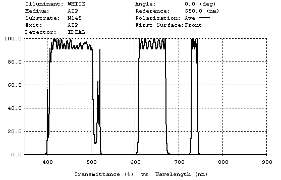 * C0 A" `+ C. I' d! j * C0 A" `+ C. I' d! j
|
|


 窥视卡
窥视卡 雷达卡
雷达卡 发表于 2011-4-1 18:36:45
 提升卡
提升卡 置顶卡
置顶卡 沉默卡
沉默卡 喧嚣卡
喧嚣卡 变色卡
变色卡 抢沙发
抢沙发 显身卡
显身卡

